仕事はデジタル、趣味はアナログ, Work is digital, hobby is analog
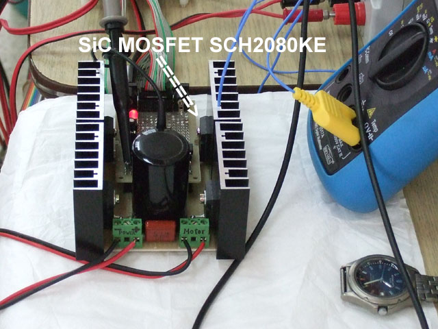
The photo looks like a D-class amplifier but this is a normal H-bridge driver with SiC MOSFET recently I have made.
For the purpose of control two motors simultaneously, dsPIC33FJ128MC802 is useful because it has two QEI and not expensive. This arrangement is just a normal one to control two motors. We are going to apply SiC MOSFET to more advanced power control.
オーディオ愛好家, Audiophiles
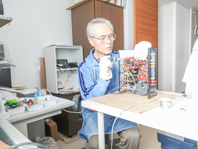
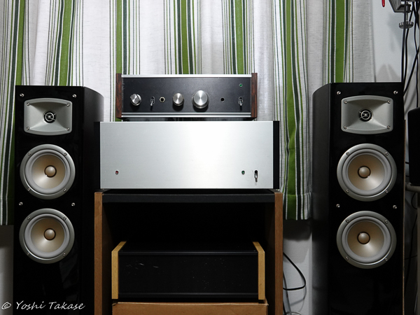
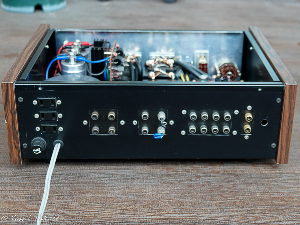
オーディオ愛好家とは高忠実度の音響再生に熱心な人々を言う。私もその一人だと思う。特にアンプの自作に熱心だった。「無線と実験」誌の製作記事を読み始めたのは1977年だ。特に「金田式DCアンプ」と呼ばれる記事に興味を持ち、プリアンプとメインアンプを作った。外国で仕事をする機会があり通算11年日本にいなかった。その間、自作アンプは休眠していた。帰国後、自作アンプの電源を入れてみたら、問題なく動作した。でも、入出力端子の錆やスイッチが気になりだした。今回、それらの部分を新品に交換しようと思い立ち、内部の部品を全部取り出した。
Audiophiles are persons who are enthusiastic about high-fidelity sound reproduction. I think I am one of them. I was particularly keen on making my own amplifier. I started reading the production articles of “Radio and Experiment” magazine in 1977. I was particularly interested in the article called “Kanada DC amplifier” and made a pre-amplifier and a main amplifier. I had the opportunity to work abroad and haven’t been in Japan for a total of 11 years. Meanwhile, the self-made amplifier was dormant. After returning to Japan, I turned on the power of my amplifier and it worked without problems. However, I was worried about the rust on the input / output terminals and the switch. This time, I decided to replace those parts with new ones, so I took out all the internal parts.
アナログプリアンプのメンテナンス, Analog pre-amplifier maintenance
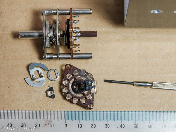
接触不良が気になるロータリースイッチを分解して接点の状態を見た。銀メッキ接点がかなりさびているので磨いて組み立てた。音の通路にスイッチを使わない方が良いが、便利さとの兼ね合いで使い続けることにした。
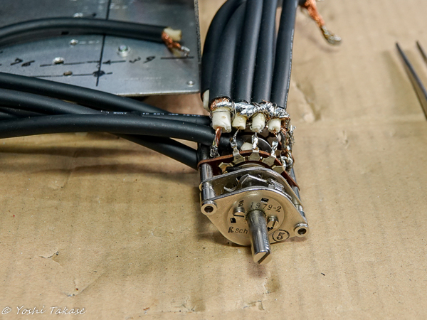
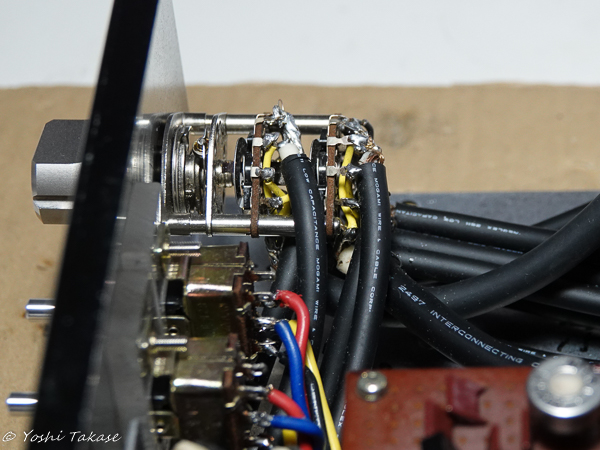
このスイッチに入力同軸ケーブルを接続する。モガミケーブルは太く固いので配線が大変だ。低静電容量の為2511の芯線は細いので動かないように固定しないと切れてしまう。時間のかかる作業だ。
I disassembled the rotary switch, which is worrisome about poor contact, and checked the contact status. It was quite rusty so I polished it and assembled it. Then connect the input cable to this switch. It takes a lot of time to wire well.
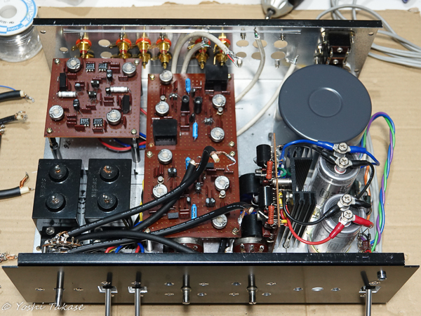
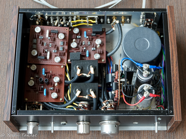
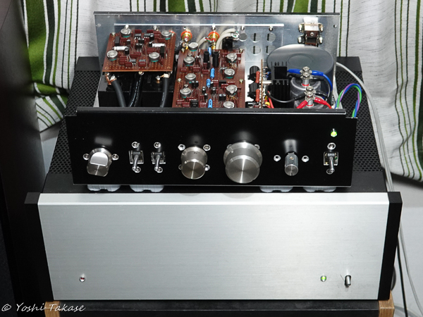
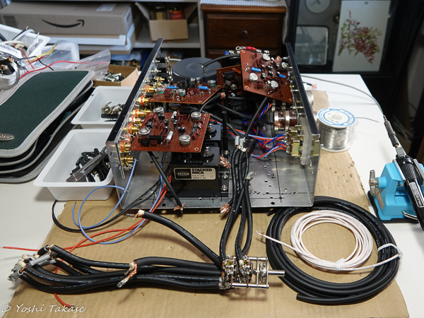
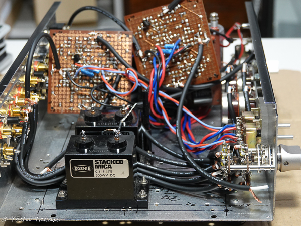
全てのパーツを元のままに戻そうと思って置いて見た。しかし、信号線に太いケーブルを使ったのでうまく治まらない。配置も再検討しよう。大きいカップリングキャパシタをヘッドアンプの下に潜り込ませて、ロータリースイッチからのケーブル配線のスペースを取った。
I put all the parts back in order to put them back. However, I used a thick cable for the signal line, so it doesn’t go well. Let’s reconsider the placement. A large coupling capacitor was slipped under the head amp to take up space for cabling from the rotary switch.
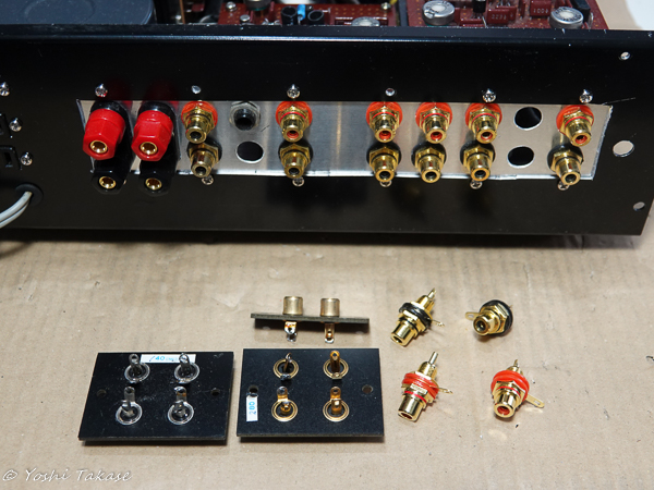
入出力新RCAジャックにケーブルをはんだ付けした後に、すべてのパーツをシャーシーに取り付けてメインアンプに接続しようとした。交換したRCAジャックにピンが入らない?良く見たら、ジャックのプラスチック絶縁体がはんだ付けの熱で溶けて変形したためだった。旧RCAジャックの絶見体はベークライトだった。非常にがっかりしたが、注意してはんだ付けすれば新RCAジャックも使えるだろう。追加購入必要だ。
After soldering the cables to the I / O RCA jacks, I tried to attach all the parts to the chassis and connect them to the main amplifier. Can’t the pin fit in the replaced RCA jack? Looking closely, it was because Jack’s plastic insulator melted and deformed due to the heat of soldering. The insulator of the old RCA jack was Bakelite. I’m very disappointed, but with careful soldering, the new RCA jacks will work. Additional purchase is required.
旧RCAジャック4連金メッキ(約30年前280円Made in Japan)
新RCAジャックMG-M RCA (4個セット598円Made in China)
Old RCA jack 4-series gold plating (about 30 years ago, 280 yen Made in Japan)
New RCA jack MG-M RCA (set of 4, 598 yen Made in China)
モガミケーブルの交換
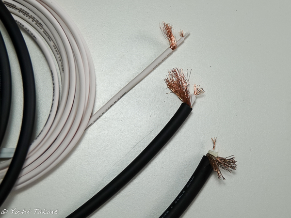
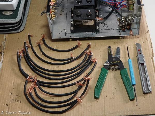
再度、入出力RCAジャックを交換しなければならない。狭い場所ではんだ付けを外す作業をすると、ケーブルの細い芯線がよく切れる。ケーブル(mogami 2511)の手持ちはもうないので、USBケーブルを切って使ってみた。しかし、これも気になる。モガミケーブルのカタログを見ると、2511はもうない。代わりに使えそうなケーブルは2520と2964だ。写真2に左から2520、2964、2511を並べてみた。2964は2511より細く芯線も丈夫そうだ。細い2520よりはるかに電気特性が優れている。2964を使うことにした。
モガミケーブルのはんだ付け

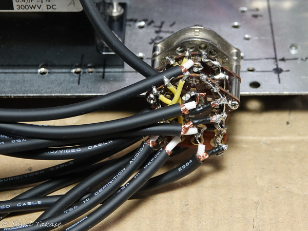
まず、アンプ出力にはんだ付けしたUSBケーブルを2964に交換した。これはそれほど大変な作業ではない。これが済むと、ロータリースイッチの配線も2511から2964に交換する意欲が出て来た。狭い場所に沢山の接点があるロータリースイッチに12本のケーブルを(ほつれたひげ銅線で)ショートさせることなくはんだ付けする作業は非常に大変だ。丁寧に作業を進めたのできれいに取り付けられた。
RCAジャックとmogami 2511の配線し直し
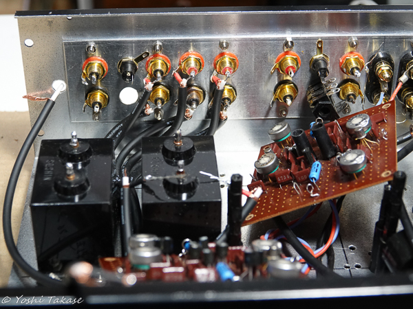
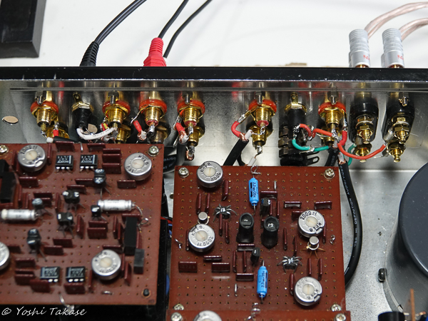
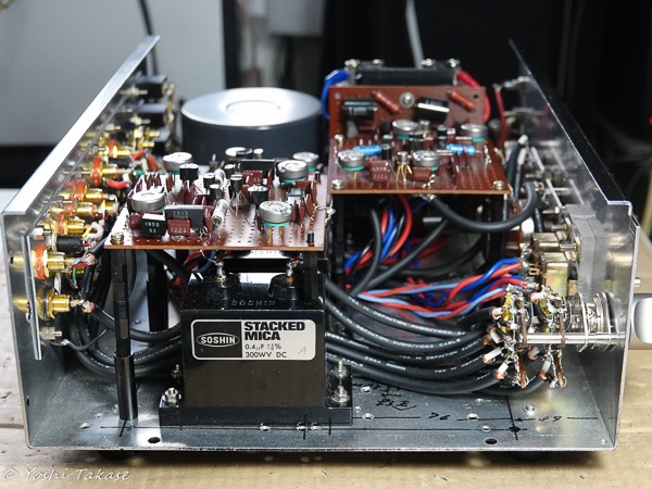
RCAジャックと新しいケーブル(mogami 2511)を購入して配線しなおした。入力RCAジャックはんだ付け部分と、それらとロータリースイッチ間のケーブル配線の写真です。交換前よりかなりすっきりした。
I bought the RCA jacks and a new cable (mogami 2511) and rewired them. The pictures show the input RCA jacks soldered parts and the cable wiring between them and the rotary switch. It was much cleaner than before the replacement.
組み立て後の音出し
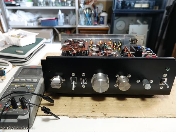
いくつかの間違いやはんだ付け不良を修正した後、マルチメータを使ってDCオフセットを調整した。そして音出しテスト、今度は正常に音が出た。良い音だ。
After fixing some mistakes and poor soldering, I adjusted the DC offset using a multimeter. And the sound output test, this time the sound came out normally. The sound is very good.
メンテナンス完了
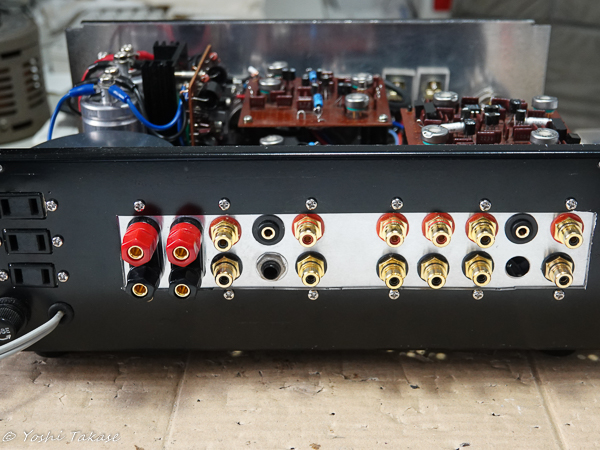
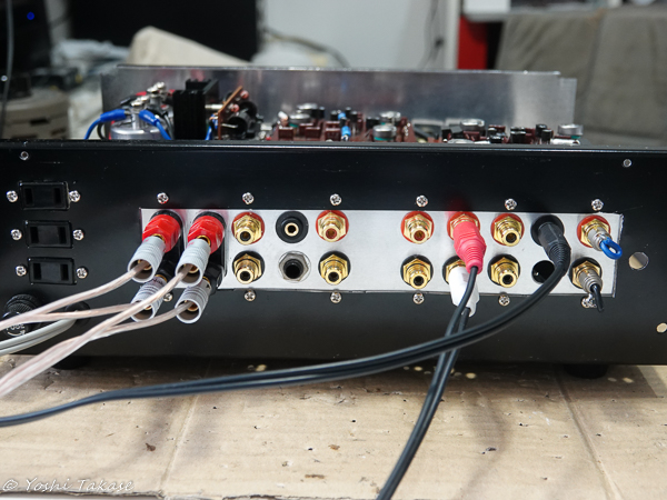
入出力RCA端子群の修正前と修正後の写真を示します。修正した結果きれいになりました。
The photos before and after the modification of the input / output RCA terminals are shown. As a result of the correction, it became beautiful.

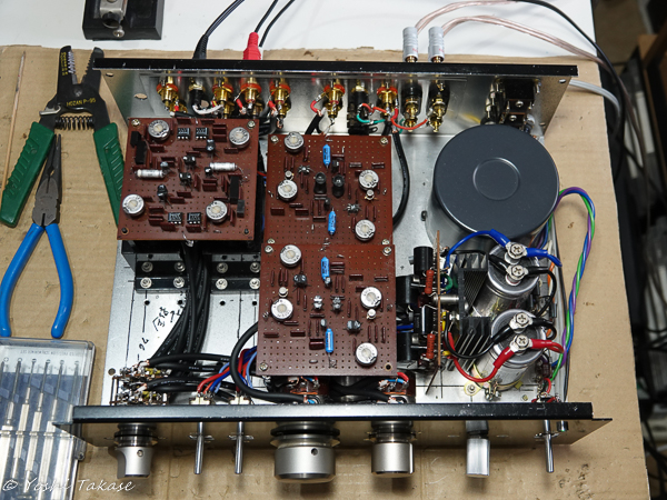
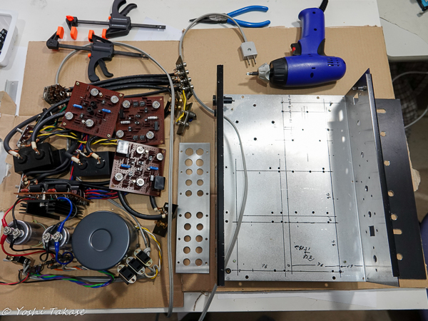
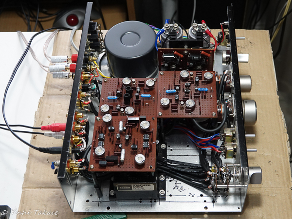
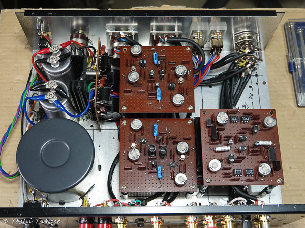
全パーツ配置の修正前と修正後の写真を示します。修正した結果配置も合理的にすっきりして新品のようになりました。
The photos before and after the correction of all parts arrangement are shown. As a result of the modification, the layout is also reasonably clean and looks like new.